

Float Glass Furnace Refractory Solutions
Eleven furnace zones, each matched to the wear mechanism that actually decides lining life — from crown and breastwall to regenerator, throat and forehearth.
Float Glass Furnace — Zone by Zone
A cross-fired float line runs a large, high-tonnage melting cycle. Each zone below carries a different load, so each is specified against its own wear mechanism rather than with a single premium grade.
Tap or click a numbered marker on the furnace cross-section to jump to the refractory configuration for that zone.
Refractory Configuration by Furnace Zone
Each zone below corresponds to a numbered marker on the furnace cross-section above. The material list for each zone is not a catalogue extract — it is the configuration our engineers apply when a float line’s operating data is known: pull rate, batch composition, furnace age and campaign target.
Doghouse & Charging Area加料池 / 投料口
Working conditions
Cold batch meets hot brickwork continuously, producing severe thermal cycling across the charging face. Batch dust and raw material fines act as an abrasive, while the doghouse is also where alkali vapour begins its upward migration into the superstructure.
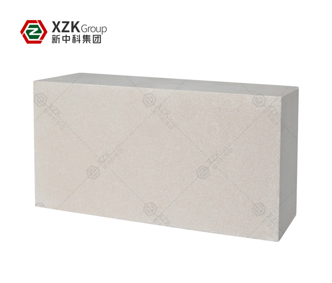
XZK-LI140
Backs the L-shaped suspended wall. Density 0.8–1.2 g/cm³, thermal conductivity ≤ 0.35–0.50 W/(m·K).
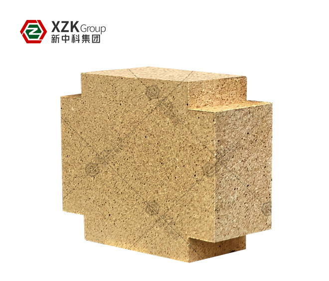
XZK-DN12
Baffle block and doghouse brickwork. Apparent porosity ≤ 12%, RUL ≥ 1470°C.
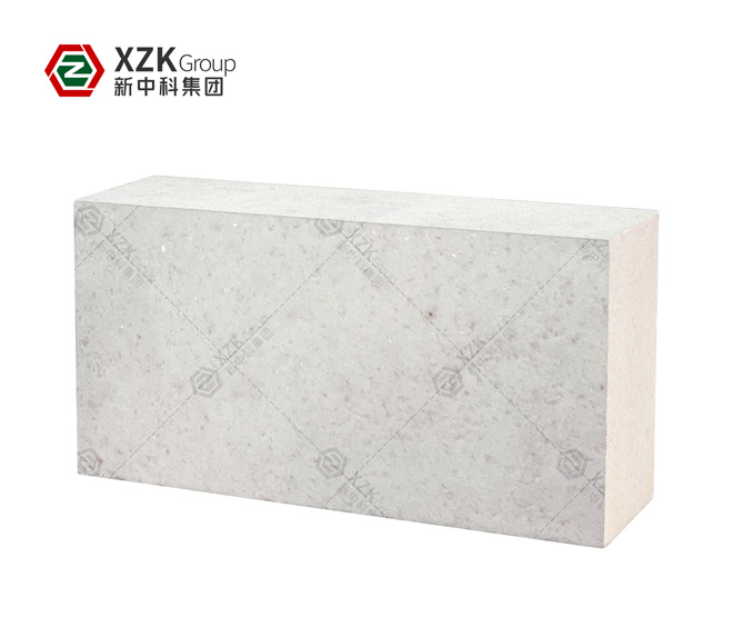
XZK-CM85
Suspended wall and charging-port facing where abrasion and thermal cycling combine. RUL ≥ 1700°C, creep ≤ 0.3%.
Crown大碹
Working conditions
The crown carries its own weight at temperature while radiating heat across its whole area, so it is both the largest heat loss and the most creep-sensitive structure in the furnace. Silica bricks develop a protective cristobalite layer at working temperature, but only if the temperature is held within their stable range.

XZK-GS
The standard crown working layer. Outstanding creep resistance under compression at temperatures above 1600°C.

XZK-SL65
Alternative crown and port crown material where alkali load is higher. Al2O3 ≥ 65%, RUL ≥ 1650°C, thermal shock ≥ 15 cycles.
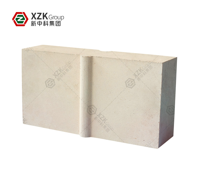
XZK-ZM12
Applied at crown areas exposed to alkali vapour. ZrO2 ≥ 12%, RUL ≥ 1680°C.
Crown Corner (Springing)大碹角 / 碹脚
Working conditions
The crown springing concentrates structural thrust from the arch and is simultaneously the main path for alkali vapour migrating upward from the melt. Reaction products expand inside the brickwork, cracking bricks and opening the joint that holds the crown in place.

XZK-ZR65-A
Dense aggregate zircon for crown corners and tuck stones. ZrO2 ≥ 65%, density ≥ 3.80 g/cm³, CCS ≥ 100 MPa. Blocks the alkali path.
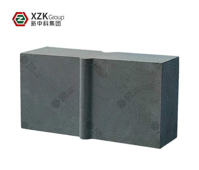
XZK-3R
Patented chrome-zirconia-corundum grade for crown joints under combined stress. Patent ZL201310431067.6.
Breastwall & Tuck Stone胸墙与挂钩砖
Working conditions
Above the melt line, the breastwall faces alkali vapour and batch dust erosion while the tuck stone carries the lateral thrust of the crown. Both are exposed to radiant heat from the melt surface and to thermal cycling during furnace reversals.
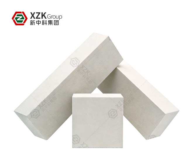
XZK-FAZS36
Breastwall working face. ZrO2 ≥ 36%, density ≥ 3.80 g/cm³, CCS ≥ 300 MPa.
XZK-CM90
Alternative breastwall material where exudation risk must be avoided. No glassy phase, Al2O3 ≥ 90%.

XZK-SAZS30
Backup layer behind fused cast and tuck stone positions. Ceramically bonded, cannot exude.
Gas Burner & Port天然气烧嘴与小炉
Working conditions
The burner block faces the most violent conditions in the furnace: localised temperatures that spike during combustion, high-velocity flame turbulence, and thermal shock on every reversal. Port crowns and burner surrounds must tolerate all three simultaneously.
XZK-3R
Engineered specifically for combined spalling, erosion and thermal shock. ZrO2 ≥ 7%, Cr2O3 ≥ 10%, thermal shock ≥ 10 cycles.
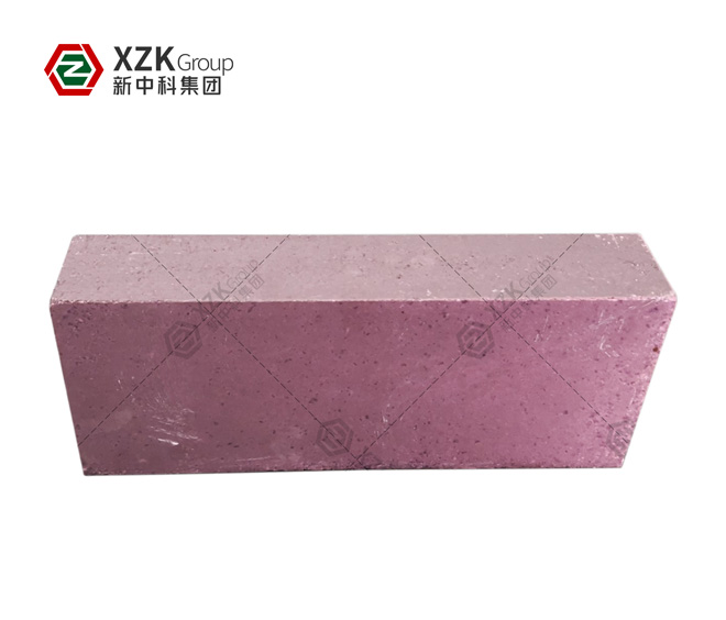
XZK-CC15 / CC30
Burner surrounds and port blocks. Cr2O3 14.5–30%, RUL ≥ 1700°C, thermal shock ≥ 12 cycles.
XZK-CM90
Port crown brickwork. Low creep under sustained load with Al2O3 ≥ 90%.
Melter Sidewall & Flux Line熔化部池壁与液面线
Working conditions
The most aggressive position in the tank. Molten glass circulates against the wall under simultaneous chemical attack and mechanical scour, and the flux line — where the brick is partly submerged and partly exposed — suffers worst because convection is most intense there.
XZK-FAZS41
Flux line and high-corrosion sidewall. ZrO2 ≥ 41%, density ≥ 3.95 g/cm³, glass phase exudation ≤ 2.5%.
XZK-FAZS36
General sidewall above and below the flux line. Balanced corrosion resistance and structural strength.
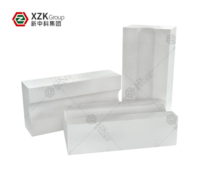
XZK-CR99
High-purity 99% alumina for positions where contamination cannot be tolerated.
Tank Bottom Paving池底铺底
Working conditions
Heavy metal contaminants in the batch settle on the bottom paving and, where joints are permeable, penetrate and drill upward into the bottom structure — the failure mode known as upward drilling, and the one that turns a worn lining into a glass leak. Charging also cycles the bottom thermally.
XZK-ZR65-A
Primary barrier against melt penetration. Density ≥ 3.80 g/cm³, low wettability by glass, CCS ≥ 100 MPa.
XZK-FAZS33
Bottom paving where corrosion resistance and thermal shock tolerance must balance. Exudation ≤ 2.0%.
XZK-SAZS30
Structural paving courses and support layers. ZrO2 ≥ 30%, RUL ≥ 1620°C.
Bottom Insulation & Sealing Layer池底保温与密封层
Working conditions
Beneath the paving, the sealing layer is the second barrier against melt penetration — and the layer where a glass leak is actually stopped. Above it, insulation reduces heat loss from the melting zone and raises the working temperature the paving sees.
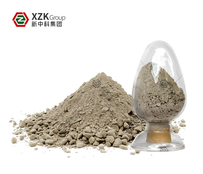
XZK-RM-ZR
Sealing sub-layer. ZrO2 ≥ 63%, density ≥ 3.3 g/cm³, CCS ≥ 50 MPa at 1200°C. Fills joints brick cannot close.
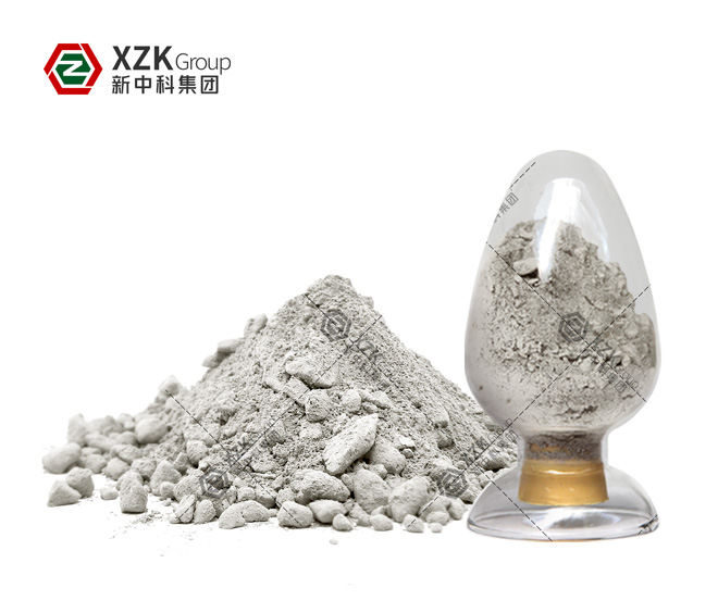
XZK-RM-AZS
Alternative sub-layer where AZS chemistry is specified. ZrO2 ≥ 30%, density ≥ 2.85 g/cm³.
XZK-LI140-1.2
Bottom insulation below the sealing layer. Highest strength grade in the LI series, CCS ≥ 8.0 MPa.
Regenerator蓄热室
Working conditions
A single chamber spans three temperature zones with three different failure mechanisms. Above 1100°C, checker bricks absorb thermal shock and high-velocity alkali scour. Between 800 and 1100°C, alkali reacts with sulphur oxides to form sulphate condensates that corrode brick and block flues. Below 800°C, the checkerwork must carry the accumulated weight of everything above it without creeping.

XZK-CC12
Hot and condensation zones. Barrel form raises heat transfer surface; Cr2O3 ≥ 12% resists sulphate attack.

XZK magnesia series
Top courses and target walls. Highest alkali resistance of any common refractory; a magnesia casing offers the best cost-performance ratio.

XZK-SL60
Structural courses and rider arch. Converts to mullite in service for volume stability under sustained load.
Throat流液洞
Working conditions
The narrowest passage in the tank and the point of highest glass velocity. The throat combines intense thermal shock with severe mechanical abrasion, and it changes the flow pattern of the entire tank if it wears unevenly.
XZK-CM90
Throat and throat hanging wall. Low creep keeps the passage dimensionally stable over a multi-year campaign.
XZK-CR99
High-purity 99% sintered alumina for maximum abrasion resistance and zero glassy phase.
XZK-ZR65-B
Where alkali resistance and thermal shock tolerance are both required. ZrO2 ≥ 65%.
Forehearth & Feeder Channel料道与流槽
Working conditions
Glass quality is decided here. Any exudation from the refractory becomes a blister, stone or cord in the finished product, and the channel is cycled continuously by gob forming. The requirement is chemical purity plus thermal stability, not maximum refractoriness.
XZK-CM85
Channel and cover blocks. Interlocking corundum-mullite network resists thermal cycling without spalling into the melt.
XZK-CR99
High-purity channel blocks where contamination risk must be minimised. No glassy phase to exude.
XZK-SAZS30
Channel and refiner positions. Ceramically bonded with no vitreous phase.
On Site — Float Glass Furnace Installations
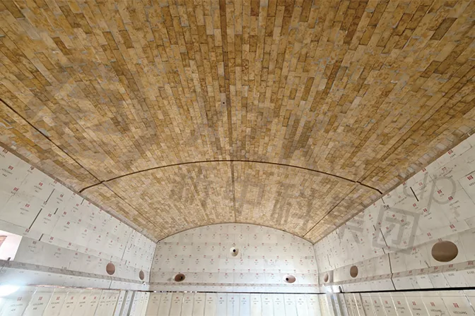
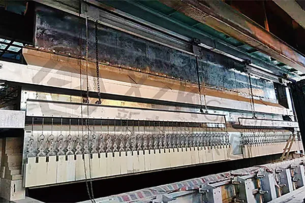
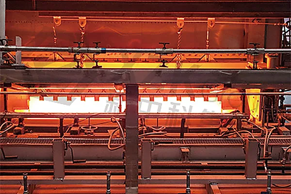
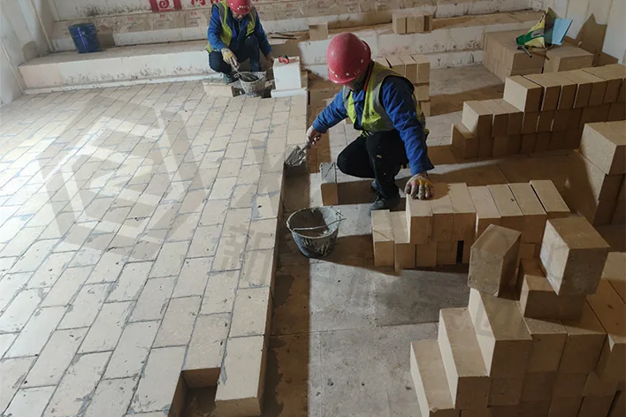
Installation photographs from float lines: the melting end crown, the suspended wall at the working end, and the tank bottom paving.
How a Float Line Configuration Is Actually Decided
A refractory specification for a float furnace is not a product list. The same nominal zone can require different grades in two furnaces of identical dimensions if batch composition, pull rate or campaign target differ. Three principles govern the configuration above.
Match grade to mechanism, not to price or prestige. Chrome corundum in the regenerator hot zone, zircon at the crown springing, fused cast AZS at the flux line — each is chosen because it defeats the specific mechanism at that position. Over-specifying the whole tank raises cost without extending life.
Treat glass contact and structure as separate problems. Where the brick meets the melt, corrosion resistance governs. Where it carries load, creep resistance governs. Different zones, different materials, and the two requirements rarely coincide.
Design joints, not just bricks. Most linings fail at joints rather than in the block. Laying drawings, joint thickness and sealing mass selection are part of the specification — for a float tank bottom, the ramming mass layer is where a leak is actually stopped.
Send us your furnace data — dimensions, pull rate, batch composition, furnace age and campaign target — and our engineers will return a zone-by-zone configuration with the relevant performance figures for each position.
Get your float furnace configuration reviewed — free
Send us your furnace data or current lining drawing. Our engineers will return a zone-by-zone configuration with performance figures for each position, and a quotation within 24 hours.
Glass Furnace Projects
Refractory configurations supplied to float, container and specialty glass producers. Each project is specified zone by zone, against the furnace data — not from a catalogue.



 WhatsApp
 WeChat
 WhatsApp
 WeChat